Sparkfun sells a few Bluetooth modules that connect to the Arduino’s UART port. From the Arduino point of view there is no practical difference between these Bluetooth modules and any other module that connects the same way like the FTDI breakout board.
So a question that comes up frequently is: Can I upload sketches through the Bluetooth module? (Read the comments section of the BlueSMiRF Silver)
And the answer is Yes!. In this post I explain how to do it from Windows using the SMiRF Silver module and an Arduino Pro 3.3V board.
The only thing preventing the BlueSMiRF from being used to upload sketches is that the modules can’t be used as-is to reset the Arduino which will start the bootloader and the upload process after that.
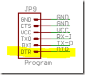
The way to reset the Arduino is through the DTR pin which is hooked to the microcontroller reset pin. However the DTR pin won’t be connected to any SMiRF line that can be driven by software. In the case of the Silver module the DTR pin will be connected to the BlueSMiRF RTS pin.
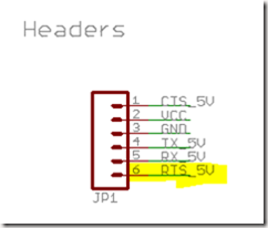
Here’s the SMiRF’s UART connector pinout (on the left) and the Arduino Pro UART pinout (on the right). The pins are connected as shown i.e. TX_5V <-> RX-I, RX_5V <-> TX-O and RTS_5V <-> DTR.
Note that there’s an error in the JP1 connector schematic: the power pins are swapped.
A few solutions
Wiring the remote DTR pin
One way of solving this problem is outlined in the comments section of the BlueSMiRF Silver:
fugalster | about a month ago 1
The answer is “yes, with a little more work.” The Arduino needs to be reset during the upload process, which is not possible via tx/rx. There is a pin on the RN42 that can act as a reset if hooked up properly. There’s also an additional pin broken out on this board, though I don’t know if it’s the pin you need. I have yet to undertake the project myself, but it is on my to do list. I’ve done the research to know it’s possible, but I can’t help you beyond that, yet.
This basically points to wiring the SMiRF’s PIO10 pin to the breakout board JP1’s ping 6. PIO10 can be used as a ‘remote DTR signal’ (see section 6.2 of the SMiRF’s Advanced User Manual) which can be driven by the device connected to the COM port i.e. your computer running the Arduino IDE.
However this is not an option if you don’t want to rework the breakout board.
Additionally you have to switch the SMiRF’s mode to the DUN or MDM SPP profiles. This is not a big deal though.
Using the Watchdog timer
But there’s another way that takes some more work but does not require any modifications to the breakout board. In a nutshell the Arduino IDE must be able to trigger a microcontroller reset through software and the rest is history.
This is what needs to get done:
1. Add code to your sketch to enable the Watchdog system reset when requested by the IDE. Note that if you want to use the Watchdog timer in your sketch for other purposes you’ll likely have to go through some hoops to keep the system reset functionality around.
2. Modify the IDE uploader code to send the right commands to your sketch to trigger the reset. Both your sketch and the uploader must agree on how long is going to take for the Watchdog reset to kick in and also the serial port speed must match whatever it is the bootloader is configured to use.
3. Upload a new bootloader to cleanup the Watchdog system reset otherwise the microcontroller will keep resetting until the board is power cycled.
Here’s what you need to do for each step
1. Add code to your sketch to enable the Watchdog system reset when requested by the IDE.
This is pretty straightforward:
#include <avr/wdt.h>

void setup()
{
  Serial.begin(57600); // Match the speed expected by the bootloader
}

void loop()
{
  if (Serial.available() > 0)
  {
    char cmd = Serial.read();
    if (cmd == 'R') // When the host sends an 'R' enable the Watchdog timer
    {
      wdt_enable(WDTO_15MS); // This is the smallest interval that can be set
    }
  }
...
}
There are a few notes about the code:
– Once the bootloader kicks in the SMiRF serial speed must match the speed the bootloader uses to configure the UART. In this case is 57600bps.
I won’t go into the details but If you need to use a different speed then there are a few options:
1. Modify the bootloader to configure the UART to a different speed.
2. Modify the IDE’s uploader code to switch the SMiRF’s speed to match that of the bootloader right after restarting the board. This however might not be possible since the SMiRF command mode can only be entered during a limited window after power on.
– The sketch code will enable the Watchdog timer after a ‘R’ character is received from the IDE. This of course can be any action as long as the IDE can drive the action and the sketch can detect it.
For example we could code the sketch so that the reset is triggered by a command received through an IR receiver where the IR transmitter is controlled directly or indirectly by the IDE.
Also remember to take note of the timer interval since you’ll also have to match that below. In this case we’ll use 15ms.
2. Modify the IDE uploader code to send the right commands to your sketch to trigger the reset. Both your sketch and the uploader must agree on how long is going to take for the Watchdog reset to kick in and also the serial port speed must match whatever it is the bootloader is configured to use.
– This requires to modify a couple of source files so get the IDE source code and setup your machine to build it, apply the following patch to the IDE sources and recompile.
Patch also here
diff --git app/src/processing/app/debug/AvrdudeUploader.java app/src/processing/app/debug/AvrdudeUploader.javaindex d5db258..3308391 100755
--- app/src/processing/app/debug/AvrdudeUploader.java
+++ app/src/processing/app/debug/AvrdudeUploader.java
@@ -82,7 +82,27 @@ public class AvrdudeUploader extends Uploader  {
       "-b" + Integer.parseInt(boardPreferences.get("upload.speed")));
     commandDownloader.add("-D"); // don't erase
     commandDownloader.add("-Uflash:w:" + buildPath + File.separator + className + ".hex:i");-
+
+	 if (boardPreferences.get("upload.use_system_reset") != null &&
+	     boardPreferences.get("upload.use_system_reset").toLowerCase().equals("true")) {	+	 	int delayInMs = 15; // Must set the sketch code to this value. 15ms is the minimum Watchdog timer value+	 	if (boardPreferences.get("upload.system_reset_delay_in_ms") != null) {
+	 		try {
+	 			delayInMs = Integer.parseInt(boardPreferences.get("upload.use_system_reset_delay_in_ms"));+	 		}
+	 		catch (Exception e) {
+	 			delayInMs = 15;
+	 		}
+	 	}
+
+		String cmd = "RESET";
+		if (boardPreferences.get("upload.system_reset_cmd") != null) {
+			cmd  = boardPreferences.get("upload.system_reset_cmd"));
+	 	}
+
+	 	triggerSystemReset(cmd, delayInMs);
+	 }
+
     if (boardPreferences.get("upload.disable_flushing") == null ||
         boardPreferences.get("upload.disable_flushing").toLowerCase().equals("false")) {       flushSerialBuffer();
diff --git app/src/processing/app/debug/Uploader.java app/src/processing/app/debug/Uploader.javaindex 245e43b..1857edb 100755
--- app/src/processing/app/debug/Uploader.java
+++ app/src/processing/app/debug/Uploader.java
@@ -71,6 +71,35 @@ public abstract class Uploader implements MessageConsumer  {

   public abstract boolean burnBootloader() throws RunnerException;

+  protected void triggerSystemReset(String cmd, int delayInMs) throws RunnerException, SerialException {+  System.out.print("Attempting to trigger system resets");
+    // Cleanup the serial buffer
+    try {
+	// This class is provided by app.processing so the port and the baud rate are taken from the Arduino preferences automatically+      Serial serialPort = new Serial();
+      byte[] readBuffer;
+      while(serialPort.available() > 0) {
+        readBuffer = serialPort.readBytes();
+        try {
+          Thread.sleep(100);
+        } catch (InterruptedException e) {}
+      }
+
+	  serialPort.write(cmd);
+	  // My Bluetooth port ends up in a bad state when it's closed right away so we need a delay here+	  Thread.sleep(1);
+      serialPort.dispose();
+	  if (delayInMs < 1)
+		delayInMs = 1;
+	  Thread.sleep(delayInMs-1);
+    } catch (SerialNotFoundException e) {
+      throw e;
+    } catch(Exception e) {
+      e.printStackTrace();
+      throw new RunnerException(e.getMessage());
+    }
+  }
+
   protected void flushSerialBuffer() throws RunnerException, SerialException {
     // Cleanup the serial buffer
     try {
|
(I’ll have to put this code on a server at some point).
– Edit the boards.txt file (build/windows/work/hardware/arduino/boards.txt) and add the following lines to the pro328 section:
pro328.upload.use_system_reset=true
pro328.upload.system_reset_cmd=R
pro328.upload.system_reset_delay_in_ms=15
pro328.upload.disable_flushing=true
Here you can set pro328.upload.system_reset_cmd to whatever string you want to use to reset the board just make sure that the skech will trigger the reset when that string is received. Also you can adjust the reset delay here which again must match the timer interval set by the sketch.
– And last but not least the SMiRF must be configured to match the port speed expected by the bootloader.
Roughly this is what you need to do.
1. Pair the module with your computer and make sure you are able to connect to the COM port. If you don’t know how to do this there’s a post here that explains how to do it.
2. Power cycle the Arduino, select the SMiRF COM port in the IDE and launch the serial monitor (you can use any other program like PUTTY to do this) and enter cmd mode by sending.
$$$
The SMiRF will reply with
CMD
Note that you have a 60s window to enter cmd mode so make sure you send the ‘$$$’ in less than a minute after power cycling the board.
3. Set the speed to 57600bps by sending
SU,57
The SMiRF will reply with
AOK
4. Leave cmd mode
—
The SMiRF will reply with
END
5. Power cycle the board
3. Upload a modified bootloader to cleanup the Watchdog system reset otherwise the microcontroller will keep resetting until the board is power cycled.
This is explained in one of my previous posts in detail
Once you complete these modifications you’ll be able to upload your sketches through the Bluetooth module wirelessly.
Enjoy!


Fantastic, It’s just I need, but I can’t copy the code to apply patch to the IDE sources and recompile. Could you put it in a file or send me it by e-mail.
Thanks in advance
Hi Jose
Just edited the post and added a link to the patch file
Cheers
This is great info! so I assume that once the modded bootloader is flashed, any IDE that knows to send the reset string will be able to reflash the arduino indefinitely as long as the new sketches still contain the watchdog reset routine correct?
That’s correct Jorge
Excellent post, thank you, this is exactly what I need. Can’t wait to try all this soon!
This didn’t work for me (I’m using a Mac, if it makes any difference) because the bluetooth serial connection is closed when the Arduino IDE hands over to avrdude. So it takes several seconds for avrdude to reopen the connection. To work around this, I left the IDE untouched, but implemented similar changes in avrdude itself. It works beautifully.
Check out my how-to for doing this with the common HC-05 Bluetooth module. You do have to solder one wire onto the breakout board but it isn’t very hard. http://makezine.com/projects/diy-arduino-bluetooth-programming-shield/